Summer Researcher with Dr. Zubaer Hossain
Mechanical Engineering
University of Delaware
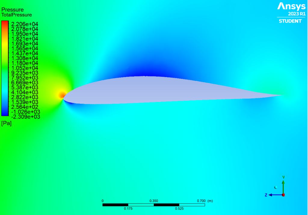
From June through August of this summer, I have been researching and optimizing airfoil rib design and testing aerospace fiber composites used in airfoils. I started out my research by learning how to use Autodesk Fusion360 and becoming familiar with some of its unique tools like generative design and topology. I found them to be extremely interesting and innovative when it comes to optimizing mass when designing new ideas. I wanted to use these tools to create an airfoil structure that could be utilized in wing design. I first started out researching and learning about airfoils and their history throughout the last 100 years. Airfoil shapes are very unique and their size, lift, and drag are optimized depending on the type of flight and uses they have. I decided to pick the NACA0012 due to the fact it was a basic airfoil with no camber that could be used on smaller aircraft and would be a great place to start and learn this new software with. To optimize the airfoil structure, I would need some boundary conditions and some data to simulate flight conditions. To achieve this I learned how to run an Ansys CFD air tunnel simulation to simulate flight at 150m/s which would be a top speed for most smaller aircraft. After running this simulation I gathered the dynamic pressure data along different sections of the airfoil seen in Figure 1.
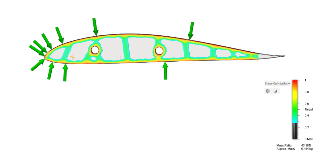
Now I had all of the conditions and data to run an accurate Fusion360 Topology experiment to determine the structure of an airfoil rib. Figure 2 depicts the topology results when running the pressure simulation of an aerospace aluminum alloy rib.
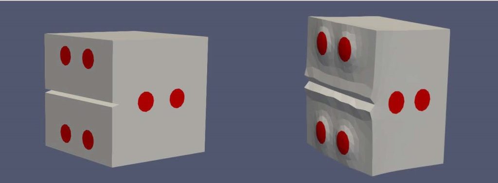
Finally, I utilized the University of Delaware’s HPC (High Performance Computing) system Caviness to simulate the pressure I calculated on different fiber composites I generated using Cubit and MEF90. I was able to identify how the composites would deform and react under pressure when exterior cracks and deformations had formed as compared to the unaltered composites seen in Figure 3. I tested different fiber orientations to simulate some configurations that could be used as lighter material in aircraft.